Installation Instructions
Straight Pin with Mounting Tool
5.2

Following these instructions will ensure that the Expander System is installed correctly and the pivot life is prolonged.
Congratulations! You have purchased a custom engineered solution to the pivot wear problem on your machine. Contact your dealer or Expander before proceeding if you have any questions.
Expander System pivot pin comes with a warranty against lug wear of 10 years / 10 000 hours in operation (whichever comes first) from the date of purchase.
The picture shows a female axle but the principle is the same for other designs.

1 Bolt. 2 Washer. 3 Sleeve. 4 Axle (Pin). 5 Bolt for mounting tool. 6 Stop screws. 7 Mounting tool 8 Allen key screws.
Preparation

Remover qualquer bucha para eliminar desgaste futuro entre bucha e olhal de montagem.

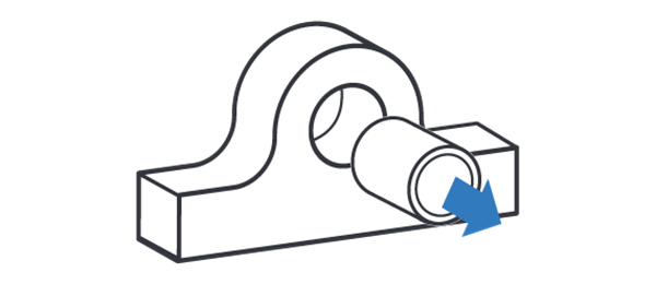
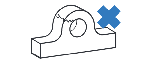
Reparar qualquer estrutura danificada ex. Trincas ou olhais tortos.

Suavize irregularidades na superfície dos furos dos olhais.

A diferença entre diâmetro min. e max. no desgaste do olhal deve ser dentro de .06” (1.5 mm) para o correto encaixe das luvas.
ATTENTION! If the worn lugs diameter at any point is 2 mm (.080”) or more over original lug diameter contact your dealer or Expander System. You will need oversized sleeves.
Installation

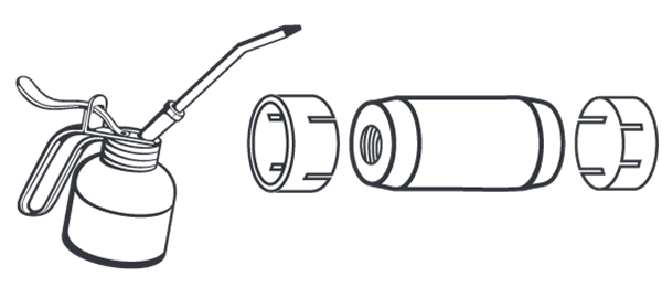
Engraxe as luvas e eixo com a graxa disponível, de preferência graxa grafitada. NÃO ENGRAXE AS ROSCAS.

NOTA! Se aplicável: posicione a saída de graxa a 90 graus para forçar a direção para minimizar a concentração de estresse na saída.

Assemble the mounting tool and bolt for mounting tool using the allen key screws. Insert the axle and position it in the bores. Install the sleeves, then the washers and fasteners. Tighten the fasteners with recommended torque.

Remove the allen key screws and mounting tool. Mount the stop screws.
Torque recommendations

Hex Bolts and Bolts for Mounting Tool
Torques M12-M24 ± 10%, M30... +30/-0%
| M12 | M14 | M16 | M20 | M24 | M30 | M36 | M42 | |
| Nm | 70 | 115 | 175 | 350 | 500 | 600 | 700 | 900 |
| lb-ft | 52 | 85 | 129 | 258 | 369 | 443 | 516 | 664 |

Porcas hexagonais: Altura padrão
Torques M12-M24 ± 10%, M30... +30/-0%
| M12 | M14 | M16 | M20 | M24 | M30 | M36 | M42 | |
| Nm | 65 | 115 | 175 | 250 | 350 | 500 | 600 | 700 |
| lb-ft | 48 | 85 | 129 | 184 | 258 | 369 | 443 | 516 |

Porcas hexagonais: Altura baixa
Todos os Torques ± 10%
| M12 | - | M16 | M20 | M24 | M30 | - | - | |
| Nm | 60 | - | 125 | 200 | 275 | 350 | - | - |
| lb-ft | 44 | - | 92 | 148 | 203 | 258 | - | - |

Porcas redondas
Todos os Torques ± 10%
| M17 | M25 | M35 | M45 | M55 | M65 | M75 | M85 | |
| Nm | 50 | 120 | 250 | 500 | 600 | 700 | 800 | 900 |
| lb-ft | 37 | 89 | 184 | 369 | 443 | 516 | 590 | 664 |
Final Check

Após o torque inicial movimente a máquina em sua amplitude total várias vezes e reconfirme o torque. Verifique o torque após 10 horas, 40 horas e em intervalos regulares de serviço para assegurar o correto assentamento das luvas.

Ensure that there is a minimum distance of 0,5mm (0.02”) between the washer and the lug. Ensure that there is a minimum distance of 0,5mm (0.02”) between the bolt for the mounting tool and the lug. ATTENTION! If the washer or bolt for the mounting tool is in contact with the lug, contact your dealer or Expander System.
Dismounting

Para desmontar o Sistema Expander, desaparafuse os espaçadores em ambas as extremidades e remova as arruelas.

Bata no eixo alternativamente do lado esquerdo e direito até a tensão nas luvas for aliviada. Remova as luvas e eixo. NÃO DANIFIQUE AS ROSCAS.
