Installation Instructions
Straight Pin with Mounting Tool
5.2

Following these instructions will ensure that the Expander System is installed correctly and the pivot life is prolonged.
Congratulations! You have purchased a custom engineered solution to the pivot wear problem on your machine. Contact your dealer or Expander before proceeding if you have any questions.
Expander System pivot pin comes with a warranty against lug wear of 10 years / 10 000 hours in operation (whichever comes first) from the date of purchase.
The picture shows a female axle but the principle is the same for other designs.

1 Bolt. 2 Washer. 3 Sleeve. 4 Axle (Pin). 5 Bolt for mounting tool. 6 Stop screws. 7 Mounting tool 8 Allen key screws.
Preparation

Usunąć wszelkie tuleje w celu wyeliminowania przyszłego zużycia się na styku miedzy tuleją, a
uchem do mocowania.

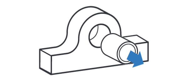
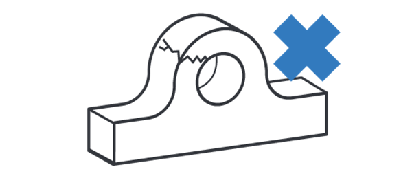
Naprawić wszelkie uszkodzenia strukturalne, np. pęknięcia lub zgięte uszy przed instalacją

Wygładzić nieregularności na powierzchniach otworów.

Różnica pomiędzy średnicą min. a max. w zużytych uszach musi mieścić się w granicach .06” (1.5 mm), aby tuleja była dobrze spasowana.
ATTENTION! If the worn lugs diameter at any point is 2 mm (.080”) or more over original lug diameter contact your dealer or Expander System. You will need oversized sleeves.
Installation

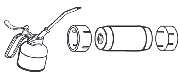
Nasmarować tuleję oraz oś
dostępnym smarem, najlepiej
grafitowym. NIE SMAROWAĆ
GWINTÓW.

UWAGA! Jeżeli można: końcówkę smarująca umieść pod kątem 90 stopni aby wymusić kierunek w celu zminimalizowania koncentracji naprężenia na końcówce.

Assemble the mounting tool and bolt for mounting tool using the allen key screws. Insert the axle and position it in the bores. Install the sleeves, then the washers and fasteners. Tighten the fasteners with recommended torque.

Remove the allen key screws and mounting tool. Mount the stop screws.
Torque recommendations

Hex Bolts and Bolts for Mounting Tool
Torques M12-M24 ± 10%, M30... +30/-0%
| M12 | M14 | M16 | M20 | M24 | M30 | M36 | M42 | |
| Nm | 70 | 115 | 175 | 350 | 500 | 600 | 700 | 900 |
| lb-ft | 52 | 85 | 129 | 258 | 369 | 443 | 516 | 664 |

Hex Nuts: Standard Height
Torques M12-M24 ± 10%, M30... +30/-0%
| M12 | M14 | M16 | M20 | M24 | M30 | M36 | M42 | |
| Nm | 65 | 115 | 175 | 250 | 350 | 500 | 600 | 700 |
| lb-ft | 48 | 85 | 129 | 184 | 258 | 369 | 443 | 516 |

Hex Nuts: Low Height
All Torques ± 10%
| M12 | - | M16 | M20 | M24 | M30 | - | - | |
| Nm | 60 | - | 125 | 200 | 275 | 350 | - | - |
| lb-ft | 44 | - | 92 | 148 | 203 | 258 | - | - |

Spanner Nuts
All Torques ± 10%
| M17 | M25 | M35 | M45 | M55 | M65 | M75 | M85 | |
| Nm | 50 | 120 | 250 | 500 | 600 | 700 | 800 | 900 |
| lb-ft | 37 | 89 | 184 | 369 | 443 | 516 | 590 | 664 |
Final Check

Po początkowym momencie obrotowym, kilkukrotnie przesunąć maszynę przez cały zakres ruchów i ponownie sprawdzić wartość momentu. Wartość momentu sprawdzać po 10, 40 godzinach lub w regularnych odstępach serwisowych, tak aby zapewnić odpowiednie posadowienie tulei rozprężnych.

Ensure that there is a minimum distance of 0,5mm (0.02”) between the washer and the lug. Ensure that there is a minimum distance of 0,5mm (0.02”) between the bolt for the mounting tool and the lug. ATTENTION! If the washer or bolt for the mounting tool is in contact with the lug, contact your dealer or Expander System.
Dismounting

W celu demontażu Systemu Expander System, odkręcić element mocujące po obydwu stronach i zdjąć podkładki.

Ostukać oś do momentu, aż naprężenie na tulei zmniejszy się, zdjąć tuleję I powtórzyć z drugiej strony. NIE USZKODZIĆ GWINTÓW.
